 The picture above shows a team launch at a slope event held at Hermanus in the Cape province, I think it is an ASW 26.
 The picture above shows a team launch at a slope event held at Hermanus in the Cape province, I think it is an ASW 26.
 With the Sungazer Scale Slope event only weeks away the preparation race is on the lovely shot above is not local , but typifies the late afternoon soaring one can experience at sunset when the "valley release " sometimes kicks in and you get to fly in "Champaigne Air"
 The glider above will be at the Sungazer ...It's Russ from Durban out doing some test flights after a serious rebuild on his lovely ASW 24 .
 Strange thing though ,he says it flies even better now that it has put on some weight , many larger gliders need a bit of weight to get them on the step , when slope soaring .Wing loadings on the large gliders can even reach 100 grams/dmsq, my big Dg500 Flies at 70 gr/dmsq but needs a bit of a blow (25-30kmh ) for launching to be safe.
 Mark swung by my office for some help with his stunning Ka6e which was built by master builder Ken Kearns .


The next step was to mark the vertical centerline and to section the block at the bulkhead breaks.


 I was going to make the actuator rods from aluminium as well until I remembered there was some 1,5mm fiberglass printed circuit board lying around on a shelf somewhere - just perfect for the job - cuts easily on the jig saw - a whole lot easier to work with than the aluminium. Measured everything carefully, drilled all the 3mm holes and below are the results:

Anyone know where I can get some neat little 3mm rivets to replace those ugly bolts?
Next step will be to build the plywood box for the unit, bolt the whole thing together and drop it into a hole in the wing.


 Like a kid with a new toy,
 .great soarer.
This glider(full size) is manufactured by Grob but is a different model to the Speed Astir tha Charl has built, it has a distinctive wing planform.
I am sure it will look great in the air-currents above the Drakenberg mountain foothills at Volksrust.


The tailplane is being built last and is blue foam with a balsa veneer ,to keep the weight down in the rear, as this glider has a long tail moment arm, and I would like to put the elevator servo in the tailplane with a direct coupling.Weight needs to be saved behind the balance point.
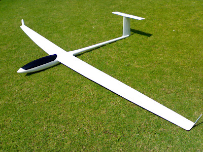
The Diana 2 is starting to look like a glider and in this photo the balsa winglets are being attached prior to glassing and spraying.
Hope it flies as sexy as it looks.
Cheers for now.

 Above, while awaiting the pilot's briefing (Lionel being handed his breakfast just before he was about to start talking) we were kept entertained by Craig Baker and his little electric pylon racer. Left, Martie again producing a great breakfast and lunch and kept us from dehydration through the scorching hot day. Right, our CD for the day, Marcel giving us his "Ja, just you try that one again, buster" look.


 Lionel flying,